Сурет:Angular Parameters of Elliptical Orbit.png
Түпнұсқа файл (1200 × 1200 пиксел, файл өлшемі: 268 КБ, MIME түрі: image/png)
| Бұл файл Wikimedia Commons? жобасынан, сондықтан басқа жобаларда да қолдануы мүмкін. Commons ашық лицензиялы медиа файл қоры. Сіз жобаға көмектесе аласыз. |
Ортаққордан қарау |
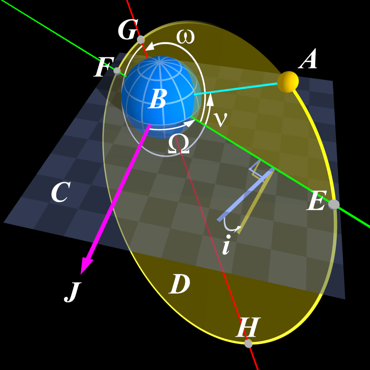
| Сипаттамасы | Raytraced image showing the concepts of inclination (i), longitude of the ascending node (Ω), argument of the periapsis (ω), and true anomaly (ν) for a "minor" object in an elliptic orbit around a larger object. |
| Күні | 23 қараша 2005 (original upload date) |
| Көзі | No machine-readable source provided. Own work assumed (based on copyright claims). |
| Авторы | No machine-readable author provided. Peo~commonswiki assumed (based on copyright claims). |
Түйін
Description (English)
Raytraced image showing the concepts of inclination (i), longitude of the ascending node (Ω), argument of the periapsis (ω), and true anomaly (ν) for a "minor" object in an elliptic orbit around a larger object.
Legend
Letters in the image denote:
- A – Minor, orbiting body
- B – Major body being orbited by A
- C – Reference plane, e.g. the ecliptic
- D – Orbital plane of A
- E – Ascending node
- F – Descending node
- G – Periapsis
- H – Apoapsis
- i – Inclination
- J – Reference direction; for orbits in or near the ecliptic, usually the vernal point
- Ω – Longitude of the ascending node
- ω – Argument of the periapsis
- ν – True anomaly
The red line is the line of apsides; going through the periapsis (G) and apoapsis (H); this line coincides wíth the major axis in the elliptical shape of the orbit
The green line is the node line; going through the ascending (E) and descending node (F); this is where the reference plane (C) intersects the orbital plane (D).
Raytracing
This image was created using the Persistence of Vision Raytracer and the scene description code below: You can use this free raytracing package and the scene description below to re-render the image in new resolutions, or modify the description and thus the image being rendered.
A few notes of caution for those who want to do their own renditions of this image:
- The "camera" (viewpoint) assumes that the image format is square (i.e. has the same number of pixels in width and height) - to achieve this, use the +w and +h command line options to set the same number of pixels in width and height, respectively.
- This image comes complete with the letter annotations, and for this, the POV-Ray installation needs access to the TrueType fonts timesbi.ttf (Times new roman, bold and italic) and symbol.ttf (for greek letters). These come as standard on a Microsoft Windows installation, so this image should at least be able to render in POV-Ray for Windows.
- A little "dirty trick" is used to put those annotations there; they are text objects placed right in front of the "camera" that "sees" the scenario. Because of this, if you modify the camera location and/or look_at-point in the code, you need to either delete the annotations or make sure they "move with" the camera.
Multiple images in one scene description
Rendering the POV-Ray scene description as shown below renders this image, showing all four angles of the orbital elements: the two remaining orbital elements not shown here are semimajor axis and eccentricity. Using this scene description, you can generate various views (isometric, normal to reference plane, normal to orbit plane) and display various features of the Keplerian orbit. You can also set the background color and whether to display the Cartesian coordinate axes.
The view variable declaration reads:
#declare view=0;
view = 0 sets the camera to an isometric view
view = 1 sets the camera to a view normal to the reference plane
view = 2 sets the camera to a view normal to the orbit plane
The backgroundColor variable declaration reads:
#declare backgroundColor = 0;
backgroundColor = 0 sets the background color as white
backgroundColor = 1 sets the background color as black
The featureCode variable declaration reads:
#declare featureCode = 0;
featureCode = 0 displays all four Keplerian orbit angles (seen here)
featureCode = 1 displays the argument of the periapsis only (see Image:Argument of Periapsis in Elliptical Orbit.png)
featureCode = 2 displays the longitude of the ascending node only (see Image:Longitude of Ascending Node in Elliptical Orbit.png)
featureCode = 3 displays the orbit inclination only (see Image:Inclination in Elliptical Orbit.png)
featureCode = 4 displays the true anomaly only (ADD IMAGE HERE)
Beskrivelse (Dansk)
Raytracet billede der demonstrerer inklination, den opstigende knudes længde og periapsisargumentet for et mindre himmellegeme i elliptisk kredsløb om et større.
Nøgle
Bogstaverne i billedet angiver:
- A – Det mindre himmellegeme
- B – Det større himmellegeme
- C – Referenceplan, f.eks. da:ekliptika
- D – Baneplan for A's omløb
- E – Nedadgående knude
- F – Periapsis
- G – Opstigende knude
- H – Apoapsis
- i – Inklination
- J – Referenceretning; for baner i eller nær ekliptikas plan typisk forårspunktet i Vædderen
- Ω – Opstigende knudes længde
- ω – Periapsisargument
Raytracing
Billedet er lavet med raytracin-programmet Persistence of Vision Raytracer, samt den scenarie-beskrivelse der er vist nedenfor. Du kan bruge dette gratis raytracing-program og beskrivelsen nedenfor til at renderer billedet i nye opløsninger, eller lave ændringer i beskrivelsen og dermed også i det endelige billede.
Et par detaljer man skal være opmærksom på hvis man vil rendere billedet:
- "Kameraet" (betragtningspunktet) i billedet går ud fra at det færdige billede får et kvadratisk format, dvs. har lige mange pixels i bredden og højden. Man bør derfor bruge kommandolinje-ordrerne +w og +h til at specificere det samme antal pixels i respektive bredden og højden.
- Billedet leveres "komplet", inklusiv bogstav-annotationerne. For at lave disse, Persistence of Vision-programmet have adgang til Truetype-skrifttyperne timesbi.ttf (Times New Roman i fed og kursiv) og symbol.ttf (for græske bogstaver). Disse er standard i en Microsoft Windows-installation, så denne scenarie-beskrivelse skulle kunne køre fejlfrit med Persistence of Vision Raytracer for Windows.
- Der er brugt et lille "sidegade-kneb" til at lave bogstav-annotationerne; de er text-objekter anbragt lige foran camera'et, så hvis man flytter på synsretningen mod motivet, skal man enten sørge for at annotationerne "flytter med" synsretningen, eller helt fjerne dem.
Fire billeder ud af én beskrivelse
Hvis man renderer scenariebeskrivelsen som den er vist nedenfor, får man dette billede der viser alle de tre parametre for en omløbsbane der er vinkler. Nogen synes at der er lidt for meget overvældende detaljemylder i billedet, så jeg ændrede beskrivelsen så den kan bruges til ikke blot hosstående billede, men også tre andre tilsvarende billeder, der blot kun beskriver én af vinklerne "ad gangen".
I linje 10 i beskrivelsen står der:
#declare View=0;
Som beskrevet i de kommentarer der starter fra linje 11, giver 0'et i ovenstående linje det kombinerede billeder der viser alle tre vinkler. Erstatter man 0'et med enten 1, 2 eller 3, får man billeder der viser én vinkel:
- for periapsisargumentet (se Image:Argument of Periapsis in Elliptical Orbit.png)
- for den opstigende knudes længde (se Image:Longitude of Ascending Node in Elliptical Orbit.png)
- for banehældning (se Image:Inclination in Elliptical Orbit.png)
Лицензиялау

|
Бұл файлды GNU Free Documentation License лицензиясының 1.2 нұсқасы бойынша немесе ескі Ашық бағдарламалық жасақтаушы қорымен жарияланған нұсқасының шарттарына сәйкес көшірмесін алуға, таратуға және/немесе өзгертуге болады. Лицензия көшірмесі GNU Free Documentation License деп аталынған бөлімде көрсетілген. |
| Бұл файл Creative Commons Attribution-Share Alike 3.0 Unported лицензиясы бойынша қолжетімді. | ||
| ||
| Лицензияландырудың бұл қасиеті осы файлға GFDL лицензиясының жаңартылуының бір бөлігі ретінде енгізілген. |
POV-Ray scene description
POV-ray image description:
/*
ClassicalOrbitalElements.pov
Description:
This scene shows the six classical orbital elements, namely:
1) semimajor axis, a (implicit)
2) eccentricity, e (implicit)
3) orbit inclinaton, i
4) argument of the ascending node, Omega
5) argument of periapsis, omega
6) true anomaly, nu
Created by:
Søren Peo Pedersen
http://da.wikipedia.org/wiki/Bruger:Peo
~2005
Updated by:
Bradley Canty
https://commons.wikimedia.org/wiki/User:Aero_BSC
2023/11/23
Updates:
1. Added true anomaly, nu
2. Added arrow preferences: ability for angles greater
than 180 deg and options for arrow head visibility
3. Added view selection (isometric, normal to reference plane,
or normal to orbital plane)
4. Added background color selection (black or white)
5. Added axes (cartesian triad) display option
6. Set the 6 classical orbital elements as variables, which
can be modified by the user
TO DO:
-- Make ascending and descending nodes move when argument of
periapsis, omega_, changed
-- Make yellow part of angle measurement thing stay in place when
argument of periapsis, omega_, changed
-- Fix aspect ratio of output image, see:
http://povray.tashcorp.net/tutorials/qd_aspect_ratio/
https://www.povray.org/documentation/view/3.6.1/153/
-- Mathematically determine vector normal to orbit plane, to
generalize the computation of the camera angle for the view
normal to the orbit plane (view 2)
================================================
*/
// VIEW PREFERENCES ----------------------------
#declare view = 0;
// 0 for isometric view
// 1 for view normal to reference plane
// 2 for view normal to orbit plane
#declare backgroundColor = 0;
// 0 for black background
// 1 for white background
#declare featureCode = 0;
// 0 for all four angles
// 1 for argument of the periapsis only
// 2 for longitude of the ascending node only
// 3 for inclination only
// 4 for true anomaly only
#declare axesOn = 0;
// 0 for X, Y, Z axes off
// 1 for X, Y, Z axes on
//---------------------------------------------
// Classical Orbital Elements (NOTICE: if these are changed, then the labels must be replaced since it changes the scene!!!)
#declare Sma=20; // Semimajor axis
#declare ecc=0.6; // Eccentricity
#declare Omega = 60; // Longitude of the ascending node, deg
#declare Incl= 60; // Inclination, deg
#declare omega_ = 140; // Argument of the periapsis, deg
#declare nu = 250; // True anomaly, deg, must be in [0,360]
// Derived variables
#declare Smi=sqrt(Sma*Sma*(1-ecc*ecc)); // Semiminor axis
#declare r = Sma*(1-ecc*ecc)/(1+ecc*cos(nu*pi/180)); // distance between major body and minor body
// Texture for latitude and longitude lines on planet
#declare txtLatLonGrid=texture {
pigment {color rgb <.4,.7,1>}
finish {ambient .6}
}
// Texture for planet
#declare txtPlanet=texture {
pigment {color rgb <0,.5,1>}
finish {ambient .6}
}
// Texture with latitudes only
#local txtLatitudes=texture {
gradient y
texture_map {
[0 txtPlanet]
#local Cnt=-9;
#while (Cnt<9)
[.5+sin(Cnt*.174533-.02)/2 txtPlanet]
[.5+sin(Cnt*.174533-.02)/2 txtLatLonGrid]
[.5+sin(Cnt*.174533+.02)/2 txtLatLonGrid]
[.5+sin(Cnt*.174533+.02)/2 txtPlanet]
#local Cnt=Cnt+3;
#end
[1 txtPlanet]
}
translate <0,-.5,0>
scale 10
}
#local Arrowhead=difference {
box {<-5,-.002,0>,<0,.002,5> rotate <0,45,0> scale <1,1,3>}
plane {<0,0,-1>,-1.5}
}
#local AxesArrowhead=difference {
box {<-6,-.0009,0>,<0,.0009,6> rotate <0,45,0> scale <1,1,3>}
plane {<0,0,-1>,-2}
}
#macro AngleArc(DegreeNumber,Radius,ArrowheadState,rgbVec)
#if (DegreeNumber <= 180)
#if (ArrowheadState = 0) //Have both arrow heads
merge {
difference {
cylinder {<0,-.002,0>,<0,.002,0>,Radius+.1}
cylinder {<0,-1,0>,<0,1,0>,Radius-.1}
plane {<0,0,1>,0 rotate <0,degrees(asin(1/Radius)),0>}
plane {<0,0,-1>,0 rotate <0,DegreeNumber-degrees(asin(1/Radius)),0>}
}
#object {Arrowhead rotate <0,-6,0> translate <Radius,0,0> rotate <0,DegreeNumber-180,0>}
#object {Arrowhead rotate <0,6,0> translate <-Radius,0,0>}
pigment {color rgb rgbVec}
finish {ambient 1}
}
#elseif (ArrowheadState = 1) //Have starting arrow head only
merge {
difference {
cylinder {<0,-.002,0>,<0,.002,0>,Radius+.1}
cylinder {<0,-1,0>,<0,1,0>,Radius-.1}
plane {<0,0,1>,0 rotate <0,degrees(asin(1/Radius)),0>}
plane {<0,0,-1>,0 rotate <0,DegreeNumber,0>}
}
#object {Arrowhead rotate <0,6,0> translate <-Radius,0,0>}
pigment {color rgb rgbVec}
finish {ambient 1}
}
#elseif (ArrowheadState = 2) //Have ending arrow head only
merge {
difference {
cylinder {<0,-.002,0>,<0,.002,0>,Radius+.1}
cylinder {<0,-1,0>,<0,1,0>,Radius-.1}
plane {<0,0,1>,0 rotate <0,0,0>}
plane {<0,0,-1>,0 rotate <0,DegreeNumber-degrees(asin(1/Radius)),0>}
}
#object {Arrowhead rotate <0,-6,0> translate <Radius,0,0> rotate <0,DegreeNumber-180,0>}
pigment {color rgb rgbVec}
finish {ambient 1}
no_shadow
}
#end
#else //DegreeNumber > 180
#if (ArrowheadState = 0) //Have both arrow heads
merge {
difference {
cylinder {<0,-.002,0>,<0,.002,0>,Radius+.1}
cylinder {<0,-1,0>,<0,1,0>,Radius-.1}
plane {<0,0,-1>,0 rotate <0,DegreeNumber-degrees(asin(1/Radius)),0>}
plane {<0,0,-1>,0 rotate <0,DegreeNumber,0>}
}
difference {
cylinder {<0,-.002,0>,<0,.002,0>,Radius+.1}
cylinder {<0,-1,0>,<0,1,0>,Radius-.1}
plane {<0,0,1>,0 rotate <0,degrees(asin(1/Radius)),0>}
}
#object {Arrowhead rotate <0,-6,0> translate <Radius,0,0> rotate <0,DegreeNumber-180,0>}
#object {Arrowhead rotate <0,6,0> translate <-Radius,0,0>}
pigment {color rgb rgbVec}
finish {ambient 1}
no_shadow
}
#elseif (ArrowheadState = 1) //Have starting arrow head only
merge {
difference {
cylinder {<0,-.002,0>,<0,.002,0>,Radius+.1}
cylinder {<0,-1,0>,<0,1,0>,Radius-.1}
plane {<0,0,-1>,0 rotate <0,DegreeNumber,0>}
}
difference {
cylinder {<0,-.002,0>,<0,.002,0>,Radius+.1}
cylinder {<0,-1,0>,<0,1,0>,Radius-.1}
plane {<0,0,1>,0 rotate <0,degrees(asin(1/Radius)),0>}
}
#object {Arrowhead rotate <0,6,0> translate <-Radius,0,0>}
pigment {color rgb rgbVec}
finish {ambient 1}
no_shadow
}
#elseif (ArrowheadState = 2) //Have ending arrow head only
merge {
difference {
cylinder {<0,-.002,0>,<0,.002,0>,Radius+.1}
cylinder {<0,-1,0>,<0,1,0>,Radius-.1}
plane {<0,0,-1>,0 rotate <0,DegreeNumber-degrees(asin(1/Radius)),0>}
plane {<0,0,-1>,0 rotate <0,DegreeNumber,0>}
}
difference {
cylinder {<0,-.002,0>,<0,.002,0>,Radius+.1}
cylinder {<0,-1,0>,<0,1,0>,Radius-.1}
plane {<0,0,1>,0 rotate <0,0,0>}
}
#object {Arrowhead rotate <0,-6,0> translate <Radius,0,0> rotate <0,DegreeNumber-180,0>}
pigment {color rgb rgbVec}
finish {ambient 1}
no_shadow
}
#end
#end
#end
#if (backgroundColor = 0)
background {color rgb <0,0,0>}
#declare arcRgbVec = <1,1,1>;
#declare nodeRgbVec = <0.7,0.7,0.7>;
#else
background {color rgb <1,1,1>}
#declare arcRgbVec = <0,0,0>;
#declare nodeRgbVec = <0.8,0.8,0.8>;
#end
#if (axesOn = 1)
//Red arrow along x-axis of inertial frame
merge {
box {<-.3,-.001,0>,<.3,.001,-9>}
#object {AxesArrowhead translate <0,0,-10>}
pigment {color rgb <.8,0,0>}
finish {ambient 1 diffuse 0}
rotate <0,0,0>
no_shadow}
//Green arrow along y-axis of inertial frame
merge {
box {<0,-.001,-.2>,<9,.001,.2>}
#object {AxesArrowhead rotate <0,-90,0> translate <10,0,0>}
pigment {color rgb <0,.8,0>}
finish {ambient 1 diffuse 0}
rotate <0,0,0>
no_shadow}
//Blue arrow along z-axis of inertial frame
merge {
box {<-.2,0,-.001>,<.2,9,.001>}
#object {AxesArrowhead rotate <90,0,0> translate <0,10,0>}
pigment {color rgb <0,0,1>}
finish {ambient 1 diffuse 0}
rotate <0,0,0>
no_shadow}
#end
// Major body ("blue sphere")
sphere {<0,0,0>,5
texture {
object {
union {
#local Cnt=0;
#while (Cnt<18)
box {<-.1,-8,-8>,<.1,8,8> rotate <0,10*Cnt+11,0>}
#local Cnt=Cnt+3;
#end
}
texture {txtLatitudes}
texture {txtLatLonGrid}
}
}
}
#if (featureCode = 0 | featureCode = 2)
merge {
//Arrow for reference direction (typically the vernal point)
box {<-.2,-.0021,0>,<.2,.0021,-23>}
#object {Arrowhead translate <0,0,-24>}
pigment {color rgb<1,0,1>}
finish {ambient 1 diffuse 0}
rotate <0,0,0>
}
#end
// Longitude of ascending node arc
#if (featureCode=0 | featureCode=2)
#object {
#if (featureCode=2)
AngleArc(Omega,18,1,arcRgbVec)
#else
AngleArc(Omega,5.75,1,arcRgbVec)
#end
rotate <0,270-Omega,0>}
#end
// Orbit plane texture
#local txtOrbitPlane=texture {
pigment {color rgbt<1,.9,0,0.5>}
finish {ambient .6}
}
// Texture for markings on orbit plane
#local txtOrbitMarking=texture {
pigment {color rgb<1,.9,0>}
finish {ambient 1 diffuse 0}
}
union {
//Cylinder to graphically find normal to orbital plane
//cylinder {<sqrt(Sma*Sma-Smi*Smi),-60,0>,<sqrt(Sma*Sma-Smi*Smi),60,0>,.1
// pigment {color rgb<1,1,0>}
// finish {ambient 1 diffuse 0}}
// Elliptic "disk" indicating the area inside the orbit
disc {0,<0,1,0>,1,0
scale <Sma,1,Smi>
translate <sqrt(Sma*Sma-Smi*Smi),0,0>
texture {
#if (featureCode=0|featureCode=3)
object {
difference {
box {<-1,-1,#if (featureCode=0) -9 #else -18 #end>,<1,1,0>}
box {<-.8,-2,-1.8>,<.6,2,1>}
box {<-2,-2,-99>,<.6,2,-2>}
#if (featureCode=0)
translate <16,0,0>
#else
translate <7,0,0>
#end
rotate <0,-40,0>
}
texture {txtOrbitPlane}
texture {txtOrbitMarking}
}
#else
txtOrbitPlane
#end
}
}
difference {
// Orbit edge outline
cylinder {<0,-.001,0>,<0,.001,0>,1
scale <Sma+.15,1,Smi+.15>
}
cylinder {<0,-1,0>,<0,1,0>,1
scale <Sma-.15,1,Smi-.15>
}
translate <sqrt(Sma*Sma-Smi*Smi),0,0>
pigment {
radial
color_map{
[0 color rgbt <1,1,0,0>]
[0.1 color rgbt <1,1,.2,0>]
[0.3 color rgbt <1,1,.3,0>]
[0.7 color rgbt <1,1,.4,.5>]
[.9 color rgbt <1,1,.5,1>]
[1 color rgbt <1,1,.6,1>]
}
rotate <0,180-nu,0>
}
finish {ambient 1 diffuse 0}
}
// Argument of periapsis arc
#if (featureCode=0)
#object {AngleArc(omega_,6.5,1,arcRgbVec)}
#end
#if (featureCode=1)
#object {AngleArc(omega_,9,1,arcRgbVec)} // Larger arc for argument of periapsis only
#end
// Minor body ("yellow moon")
#declare minorBodyPosVec = <0,0,0>;
#if (nu < 90)
#declare minorBodyXpos = -r*cos(nu*pi/180);
#declare minorBodyZpos = -r*sin(nu*pi/180);
#else
#declare minorBodyXpos = r*cos(nu*pi/180 - pi);
#declare minorBodyZpos = r*sin(nu*pi/180 - pi);
#end
#declare minorBodyPosVec = <minorBodyXpos,0,minorBodyZpos>;
sphere {
minorBodyPosVec,1
pigment {color rgb <1,.8,0>}
finish {ambient .6}
}
#if (featureCode = 0 | featureCode = 4)
// Line from major body to minor body
cylinder {
<0,0,0>,
minorBodyPosVec,.1
pigment {color rgb<0,1,1>}
finish {ambient 1 diffuse 0}
}
// True anomaly arc
#object {AngleArc(nu,7.25,1,arcRgbVec) rotate <0,360-nu,0>}
#end
// Line of apsides
#if (featureCode = 0 | featureCode = 1 | featureCode = 4)
cylinder {
<sqrt(Sma*Sma-Smi*Smi)-Sma-50,0,0>,
<sqrt(Sma*Sma-Smi*Smi)+Sma+50,0,0>,.1
pigment {color rgb<1,0,0>}
finish {ambient 1 diffuse 0}
}
#end
#if (featureCode = 0 | featureCode = 1 | featureCode = 4)
// Periapsis node
sphere {<sqrt(Sma*Sma-Smi*Smi)-Sma,0,0>,.5 pigment {color rgb nodeRgbVec} finish {ambient 1 diffuse 0}}
#end
#if (featureCode = 0 | featureCode = 1 | featureCode = 4)
// Apoapsis node
sphere {<sqrt(Sma*Sma-Smi*Smi)+Sma,0,0>,.5 pigment {color rgb nodeRgbVec} finish {ambient 1 diffuse 0}}
#end
no_shadow
// Order of elements in rotation tuple DOES MATTER: in rotate function, rotation occurs about x-axis first, then y-axis, then z-axis
// Order of applying rotations to orient the ellipse DOES MATTER:
// 1) rotate about z-axis by argument of the periapsis, omega
// 2) rotate about x-axis by inclination, inc
// 3) rotate about z-axis by longitude of the ascending node, Omega
// Note: Coordinate frame is screwed up: it is (y,z,x)... SHOULD FIX THIS
rotate <0,-90,0> // this rotations is needed because the ellipse was not intially oriented correctly... SHOULD FIX THIS
rotate <0,-omega_,0> //130 deg rotation about z-axis (but actually the screwed up y axis)
rotate <0,0,Incl> //then 60 deg rotation about x-axis (but actuall the screwed up z axis)
rotate <0,-Omega,0> //then 60 deg rotation about z-axis (but actually the screwed up y axis)
}
union {
#if (featureCode != 4)
// Line of nodes
cylinder {<-60,0,0>,<60,0,0>,.1 pigment {color rgb<0,1,0>} finish {ambient 1 diffuse 0}}
// Ascending node
sphere {<23.6,0,0>,.5 pigment {color rgb nodeRgbVec} finish {ambient 1 diffuse 0}}
// Descending node
sphere {<-8.8,0,0>,.5 pigment {color rgb nodeRgbVec} finish {ambient 1 diffuse 0}}
#end
#if (featureCode=0)
// Measure of inclination
#object {AngleArc(Incl,8,2,arcRgbVec)
rotate <90,-90,0> translate <16.8,0,0>}
no_shadow
#end
#if (featureCode=3)
// Measure of inclination
#object {AngleArc(Incl,17,0,arcRgbVec)
rotate <90,-90,0> translate <7.8,0,0>}
no_shadow
#end
rotate <0,90-Omega,0>
}
//Texture for reference plane
#local RefPlaneChecker=texture { // Texture for
pigment {checker // reference
color rgbt<.6,.7,1,.5> // plane
color rgbt<.48,.56,.8,.5>
scale 3
}
finish {ambient .4}
}
//Texture for markings on reference plane
#local RefPlaneMark=texture { // Texture for
pigment {checker // markings on
color rgbt<.6,.7,1,0> // reference
color rgbt<.48,.56,.8,0> // plane
scale 3
}
finish {ambient 1 diffuse 0}
}
merge { // The reference plane
triangle {<-9,0,-21>,<21,0,-21>,<-9,0,9>}
triangle {<21,0,9>,<21,0,-21>,<-9,0,9>}
texture {
#if (featureCode=0|featureCode=3)
object {
difference {
box {<-1,-1,#if (featureCode=0) -9 #else -18 #end>,<1,1,0>}
box {<-.8,-2,-1.8>,<.6,2,1>}
box {<-2,-2,-99>,<.6,2,-2>}
#if (featureCode=0)
translate <16,0,0>
#else
translate <7,0,0>
#end
rotate <0,90-Omega,0>
}
texture {RefPlaneChecker}
texture {RefPlaneMark}
}
#else
RefPlaneChecker
#end
}
}
#switch (view)
#case (0) // Isometric view
union { // A, B, C, and D are common for all four images...
// A: Orbiting body
text {ttf "timesbi.ttf","A",.001,0
scale 0.0035 translate <.0135,.014,0>}
// B: Body being orbited
text {ttf "timesbi.ttf","B",.001,0
scale .0035 translate <-.0045,.0092,0>}
// C: Reference plane
text {ttf "timesbi.ttf","C",.001,0
scale .0035 translate <-.016,-.002,0>}
// D: Orbital plane of A
text {ttf "timesbi.ttf","D",-.001,0
scale .0035 translate <-.002,-.013,0>}
// Deal with "special cases" in each of the four images:
#switch (featureCode)
#case (0) // Letter markings for viewing all four angles
// "Upper-case" Omega at the longitude of ascending node
text {ttf "symbol.ttf","W",.001,0
scale .0035 translate <-.002,0.0038,0>}
// "Lower-case" nu at the true anomaly
text {ttf "symbol.ttf","\u006E",.001,0
scale .0035 translate <.0034,0.007,0>}
// "Lower-case" omega at the argument of the periapsis
text {ttf "symbol.ttf","w",.001,0
scale .0035 translate <-0.001,.017,0>}
// "Lower-case" i at the inclination
text {ttf "timesbi.ttf","i",.001,0
scale .0035 translate <.0045,-.0083,0>}
// E: Ascending node
text {ttf "timesbi.ttf","E",.001,0
scale .0035 translate <.0145,-.003,0>}
// F: Descending node
text {ttf "timesbi.ttf","F",.001,0
scale .0035 translate <-.011,.013,0>}
// G: Periapsis
text {ttf "timesbi.ttf","G",.001,0
scale .0035 translate <-.008,.0175,0>}
// H: Apoapsis
text {ttf "timesbi.ttf","H",.001,0
scale .0035 translate <.006,-.0182,0>}
// J: Reference direction, e.g. vernal point
text {ttf "timesbi.ttf","J",.001,0
scale .0035 translate <-.0145,-.014,0>}
#break
#case (1) // Letter markings for viewing only argument of periapsis
// "lower-case" omega at argument of periapsis
text {ttf "symbol.ttf","w",.001,0
scale .007 translate <.0053,.01,0>}
// E: Ascending node
text {ttf "timesbi.ttf","E",.001,0
scale .0035 translate <.0149,-.003,0>}
// F: Periapsis
text {ttf "timesbi.ttf","F",-.001,0
scale .0035 translate <-.0085,.0167,0>}
#break
#case (2) // Letter markings for viewing only longitude of ascending node
// "Upper-case" Omega at longitude of ascending node
text {ttf "symbol.ttf","W",.001,0
scale .007 translate <0.0005,-.009,0>}
// E: Ascending node
text {ttf "timesbi.ttf","E",.001,0
scale .0035 translate <.0145,-.003,0>}
// F: Descending node
text {ttf "timesbi.ttf","F",.001,0
scale .0035 translate <-.011,.013,0>}
#break
#case (3) // Letter markings for viewing only the inclination
// E: Ascending node
text {ttf "timesbi.ttf","E",.001,0
scale .0035 translate <.0145,-.003,0>}
// F: Descending node
text {ttf "timesbi.ttf","F",.001,0
scale .0035 translate <-.011,.013,0>}
// "Lower-case" i at the inclination
text {ttf "timesbi.ttf","i",.001,0
scale .007 translate <-.011,-.012,0>}
#break
#case (4) // Letter markings for viewing only the true anomaly
// "Lower-case" nu at the true anomaly
text {ttf "symbol.ttf","\u006E",.001,0
scale .007 translate <.0015,0.002,0>}
// G: Periapsis
text {ttf "timesbi.ttf","G",.001,0
scale .0035 translate <-.008,.0175,0>}
// H: Apoapsis
text {ttf "timesbi.ttf","H",.001,0
scale .0035 translate <.006,-.0182,0>}
#break
#end
// Common settings for the letters in the image
#if (backgroundColor = 0)
pigment {color rgb<1,1,1>}
#else
pigment {color rgb<0,0,0>}
#end
finish {ambient 1 diffuse 0}
no_shadow
translate <0,0,.04>
rotate <51.3765,-13.62699,0>
translate <11,26,-33>
}
#case(1) // View normal to the reference plane
union { // A, B, C, and D are common for all four images...:
// A: Orbiting body
text {ttf "timesbi.ttf","A",.001,0
scale 0.0035 translate <.0095,.0038,0>}
// B: Body being orbited
text {ttf "timesbi.ttf","B",.001,0
scale .0035 translate <-.009,.004,0>}
// C: Reference plane
text {ttf "timesbi.ttf","C",.001,0
scale .0035 translate <-.011,-.007,0>}
// D: Orbital plane of A
text {ttf "timesbi.ttf","D",-.001,0
scale .0035 translate <.0075,-.008,0>}
// Deal with "special cases" in each of the four images:
#switch (featureCode)
#case (0) // Letter markings for viewing all four angles
// "Upper-case" Omega at the longitude of ascending node
text {ttf "symbol.ttf","W",.001,0
scale .0035 translate <-.004,-0.0022,0>}
// "Lower-case" nu at the true anomaly
text {ttf "symbol.ttf","\u006E",.001,0
scale .0035 translate <.0012,0.0018,0>}
// "Lower-case" omega at the argument of the periapsis
text {ttf "symbol.ttf","w",.001,0
scale .0035 translate <-0.0035,.0085,0>}
// "Lower-case" i at the inclination
text {ttf "timesbi.ttf","i",.001,0
scale .0035 translate <.003,-.007,0>}
// E: Ascending node
text {ttf "timesbi.ttf","E",.001,0
scale .0035 translate <.0135,-.005,0>}
// F: Descending node
text {ttf "timesbi.ttf","F",.001,0
scale .0035 translate <-.0153,.0065,0>}
// G: Periapsis
text {ttf "timesbi.ttf","G",.001,0
scale .0035 translate <-.01,.012,0>}
// H: Apoapsis
text {ttf "timesbi.ttf","H",.001,0
scale .0035 translate <.005,-.013,0>}
// J: Reference direction, e.g. vernal point
text {ttf "timesbi.ttf","J",.001,0
scale .0035 translate <-0.0051,-.0174,0>}
#break
#case (1) // Letter markings for viewing only argument of periapsis
// "lower-case" omega at argument of periapsis
text {ttf "symbol.ttf","w",.001,0
scale .007 translate <-.002,.01,0>}
// E: Ascending node
text {ttf "timesbi.ttf","E",.001,0
scale .0035 translate <.0135,-.005,0>}
// F: Descending node
text {ttf "timesbi.ttf","F",.001,0
scale .0035 translate <-.0153,.0065,0>}
// G: Periapsis
text {ttf "timesbi.ttf","G",.001,0
scale .0035 translate <-.0125,.012,0>}
// H: Apoapsis
text {ttf "timesbi.ttf","H",.001,0
scale .0035 translate <.005,-.013,0>}
#break
#case (2) // Letter markings for viewing only longitude of ascending node
// "Upper-case" Omega at longitude of ascending node
text {ttf "symbol.ttf","W",.001,0
scale .007 translate <-0.0015,-.0075,0>}
// E: Ascending node
text {ttf "timesbi.ttf","E",.001,0
scale .0035 translate <.0135,-.005,0>}
// F: Descending node
text {ttf "timesbi.ttf","F",.001,0
scale .0035 translate <-.0153,.0065,0>}
// J: Reference direction, e.g. vernal point
text {ttf "timesbi.ttf","J",.001,0
scale .0035 translate <-0.0051,-.0174,0>}
#break
#case (3) // Letter markings for viewing only the inclination
// E: Ascending node
text {ttf "timesbi.ttf","E",.001,0
scale .0035 translate <.0135,-.005,0>}
// F: Descending node
text {ttf "timesbi.ttf","F",.001,0
scale .0035 translate <-.0153,.0065,0>}
// "Lower-case" i at the inclination
text {ttf "timesbi.ttf","i",.001,0
scale .007 translate <-.005,-.012,0>}
#break
#case (4) // Letter markings for viewing only the true anomaly
// "Lower-case" nu at the true anomaly
text {ttf "symbol.ttf","\u006E",.001,0
scale .007 translate <.0005,-0.0015,0>}
// G: Periapsis
text {ttf "timesbi.ttf","G",.001,0
scale .0035 translate <-.01,.012,0>}
// H: Apoapsis
text {ttf "timesbi.ttf","H",.001,0
scale .0035 translate <.005,-.013,0>}
#break
#end
// Common settings for the letters in the image
#if (backgroundColor = 0)
pigment {color rgb<1,1,1>}
#else
pigment {color rgb<0,0,0>}
#end
finish {ambient 1 diffuse 0}
no_shadow
rotate <90,0,0>
translate <6,44.96,-6>
}
#case (2) // View normal to the orbital plane
union { // A, B, C, and D are common for all four images...
// A: Orbiting body
text {ttf "timesbi.ttf","A",.001,0
scale 0.0025 translate <0.0034,.0533,0>}
// B: Body being orbited
text {ttf "timesbi.ttf","B",.001,0
scale .0025 translate <-.007,.0475,0>}
// C: Reference plane
text {ttf "timesbi.ttf","C",.001,0
scale .0025 translate <0.01,0.0452,0>}
// Deal with "special cases" in each of the four images:
#switch (featureCode)
#case (0) // Letter markings for viewing all four angles
// "Upper-case" Omega at the longitude of ascending node
text {ttf "symbol.ttf","W",.001,0
scale .0025 translate <-0.0025,.0455,0>}
// "Lower-case" nu at the true anomaly
text {ttf "symbol.ttf","\u006E",.001,0
scale .0025 translate <-.00084,0.0484,0>}
// "Lower-case" omega at the argument of the periapsis
text {ttf "symbol.ttf","w",.001,0
scale .0025 translate <-.005,0.052,0>}
// "Lower-case" i at the inclination
text {ttf "timesbi.ttf","i",.001,0
scale .0025 translate <.0053,0.043,0>}
// E: Ascending node
text {ttf "timesbi.ttf","E",.001,0
scale .0025 translate <.0087,.0483,0>}
// F: Descending node
text {ttf "timesbi.ttf","F",.001,0
scale .0025 translate <-0.0127,0.04692,0>}
// G: Periapsis
text {ttf "timesbi.ttf","G",.001,0
scale .0025 translate <-.0111,0.0505,0>}
// H: Apoapsis
text {ttf "timesbi.ttf","H",.001,0
scale .0025 translate <.0092,0.034,0>}
// J: Reference direction, e.g. vernal point
text {ttf "timesbi.ttf","J",.001,0
scale .0025 translate <0.0025,0.039,0>}
#break
// D: Orbital plane of A
text {ttf "timesbi.ttf","D",-.001,0
scale .0025 translate <-.003,0.036,0>}
#case (1) // Letter markings for viewing only argument of periapsis
// "lower-case" omega at argument of periapsis
text {ttf "symbol.ttf","w",.001,0
scale .005 translate <-.006,0.0535,0>}
// E: Ascending node
text {ttf "timesbi.ttf","E",.001,0
scale .0025 translate <0.0085,0.0483,0>}
// F: Descending node
text {ttf "timesbi.ttf","F",.001,0
scale .0025 translate <-0.0127,0.04692,0>}
// G: Periapsis
text {ttf "timesbi.ttf","G",.001,0
scale .0025 translate <-.0111,0.0505,0>}
// H: Apoapsis
text {ttf "timesbi.ttf","H",.001,0
scale .0025 translate <.0092,0.034,0>}
// D: Orbital plane of A
text {ttf "timesbi.ttf","D",-.001,0
scale .0025 translate <-.003,0.036,0>}
#case (2) // Letter markings for viewing only longitude of ascending node
// "Upper-case" Omega at the longitude of ascending node
text {ttf "symbol.ttf","W",.001,0
scale .0045 translate <0.0042,.0425,0>}
// E: Ascending node
text {ttf "timesbi.ttf","E",.001,0
scale .0025 translate <.0087,.0483,0>}
// F: Descending node
text {ttf "timesbi.ttf","F",.001,0
scale .0025 translate <-0.0127,0.04692,0>}
// J: Reference direction, e.g. vernal point
text {ttf "timesbi.ttf","J",.001,0
scale .0025 translate <0.0025,0.039,0>}
// D: Orbital plane of A
text {ttf "timesbi.ttf","D",-.001,0
scale .0025 translate <-.003,0.036,0>}
#break
#case (3) // Letter markings for viewing only the inclination
// "Lower-case" i at the inclination
text {ttf "timesbi.ttf","i",.001,0
scale .005 translate <-.003,0.038,0>}
// E: Ascending node
text {ttf "timesbi.ttf","E",.001,0
scale .0025 translate <.0087,.0483,0>}
// F: Descending node
text {ttf "timesbi.ttf","F",.001,0
scale .0025 translate <-0.0127,0.04692,0>}
// "Lower-case" i at the inclination
text {ttf "timesbi.ttf","i",.001,0
scale .007 translate <-.011,-.012,0>}
// D: Orbital plane of A
text {ttf "timesbi.ttf","D",-.001,0
scale .0025 translate <0.0025,0.036,0>}
#break
#case (4) // Letter markings for viewing only the true anomaly
// "Lower-case" nu at the true anomaly
text {ttf "symbol.ttf","\u006E",.001,0
scale .005 translate <-.0011,0.0445,0>}
// D: Orbital plane of A
text {ttf "timesbi.ttf","D",-.001,0
scale .0025 translate <-.003,0.036,0>}
// G: Periapsis
text {ttf "timesbi.ttf","G",.001,0
scale .0025 translate <-.0111,0.0505,0>}
// H: Apoapsis
text {ttf "timesbi.ttf","H",.001,0
scale .0025 translate <.0092,0.034,0>}
#break
#end
// Common settings for the letters in the image
#if (backgroundColor = 0)
pigment {color rgb<1,1,1>}
#else
pigment {color rgb<0,0,0>}
#end
finish {ambient 1 diffuse 0}
no_shadow
rotate <30,30,0>
translate <-12.45,14.65,-40>
}
#end
// Viewpoint - DO NOT CHANGE without recalculating the translate and rotate above,
// which align the letter markings in the image with the camera's viewing angle
#if (view = 0)
camera {
right <1,0,0> up <0,1,0>
//right <1.33,0,0> up <0,1,0>
location <11,26,-33>
look_at <3,-16.5,0>
angle 58
}
#elseif (view = 1)
camera {
right <1,0,0> up <0,1,0>
location <6,45,-6>
look_at <6,0,-6>
angle 54
}
#elseif (view = 2)
camera {
right <1,0,0> up <0,1,0>
location <-12.45,14.7,-40>
look_at <6.032,-6.680,-7.936>
angle 58
}
#end
light_source {<10000,5000,-5000> color rgb 1}
Файл тарихы
Файл сол кезде қалай көрінгенін көру үшін күн/уақыт дегенге басыңыз.
| Күн/Уақыт | Нобай | Өлшемдер | Қатысушы | Пікір | |
|---|---|---|---|---|---|
| қазіргі | 22:52, 2023 ж. қарашаның 29 | | 1200 × 1200 (268 КБ) | Aero BSC | Added true anomaly angle, line from major body to minor body, and directionality of arrows |
| 21:49, 2005 ж. қарашаның 27 |  | 1200 × 1200 (197 КБ) | Peo~commonswiki | Reordered letter annotations. Scene description modified to render several images. | |
| 02:58, 2005 ж. қарашаның 24 |  | 1200 × 1200 (198 КБ) | Peo~commonswiki | == Beskrivelse == Raytraced image showing the concepts of inclination, longitude of the ascending node, and argument of the periapsis for a "minor" object in an elliptic orbit around a larger object. Raytraced using the Persistence of Vision Raytracer an |
Файл қолданылуы
Бұл файлды мына 2 бет қолданады:
Глобалды файл қолданылуы
Бұл файл келесі басқа уикилерде қолданылады:
- anp.wikipedia.org жобасында қолданылуы
- ar.wikipedia.org жобасында қолданылуы
- arz.wikipedia.org жобасында қолданылуы
- be.wikipedia.org жобасында қолданылуы
- bg.wikipedia.org жобасында қолданылуы
- bn.wikipedia.org жобасында қолданылуы
- ca.wikipedia.org жобасында қолданылуы
- cdo.wikipedia.org жобасында қолданылуы
- ckb.wikipedia.org жобасында қолданылуы
- cv.wikipedia.org жобасында қолданылуы
- de.wikipedia.org жобасында қолданылуы
- en.wikipedia.org жобасында қолданылуы
- es.wikipedia.org жобасында қолданылуы
- eu.wikipedia.org жобасында қолданылуы
- fr.wikipedia.org жобасында қолданылуы
- fr.wiktionary.org жобасында қолданылуы
- gl.wikipedia.org жобасында қолданылуы
- hr.wikipedia.org жобасында қолданылуы
- hy.wikipedia.org жобасында қолданылуы
- it.wikipedia.org жобасында қолданылуы
- ja.wikipedia.org жобасында қолданылуы
Бұл файлдың глобалды қолданылуын көбірек көру.